


The drill with a stick shift are probably familiar. engine. clutch. Transmission. When you release your foot from the clutch, the engine stops. Stomp it down, and you move. This is a mechanical handshake that is interrupted when necessary. But what about slam the door on an automatic? There is no clutch pedal. No disconnection. However, when the car is stopped, the engine hums.
How does this work?
The answer is a torque converter.
Although it sounds like a complex technological marvel, it is essentially a fluid coupling. Replaces the mechanical clutch in a manual transmission. Without this, automatic car would stall every time the brake is applied. This allows the engine to spin independently of the wheels. This is not magic. This is fluid mechanics.
Physics of Twist
Let’s make one thing clear. Torque is not speed. It is the twisting force.
Turning the crankshaft produces torque. More torque means you can accelerate faster. It is the energy behind the movement. A manual transmission connects the engine’s torque directly to the transmission. The wheels are turning. The engine is running. They are locked together.
This is not the case with the automatic transmission.
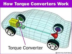
The torque converter is located between the engine and the gearbox. It uses transmission fluid to transfer power. When you stop at a red light, the engine revs up. The converter spins. But the transmission input shaft does not have to. The fluid allows for slippage. This slippage is the key to not killing the engine.
Most people confuse automatic transmissions with modern CVT transmissions or semi-manual transmissions. We are talking about a traditional planetary automatics here. The kind you have probably driven since the 1950s. These systems are completely dependent on this fluid coupling. New technologies such as continuously variable transmissions (CVTs) use belts and pulleys. The torque converter is not used. But what about classic automatic transmissions? It’s all about liquids.
Inside the converter
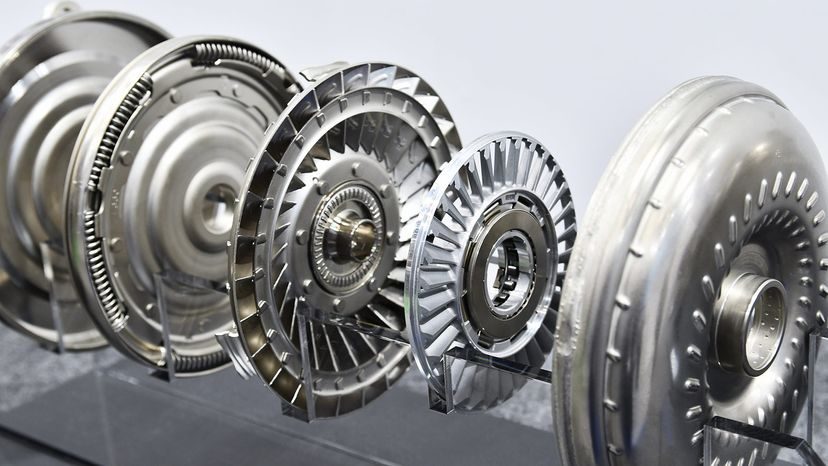
This device looks like a large, heavy metal nut. That’s all you can see from the outside. But inside, three main components work together.
- Pump impeller (connected to the engine)
- Turbine (connected to the gearbox)
- Stator (sitting in between)
The engine spins the pump. The pump injects transmission fluid into the turbine. The turbine is spinning. The turbine rotates the input shaft of the transmission. The car moves.
But here’s where it gets interesting. If it were just a pump and a turbine have very low efficiency. Power would be lost. Enter the stator.
The stator changes the direction of the fluid returning from the turbine. Amplify the torque. That’s why it’s called a “torque converter”. At low speeds, the torque converter multiplies the engine’s torque. This gives you an initial boost when you hit the gas pedal from a stop. Without this multiplication, automatic cars would feel slow.
The stator stays in one direction with the help of a one-way clutch. This allows you to effectively change the direction of the fluid during acceleration. Once the car picks up speed, the fluid flow changes. The stator rotates freely. It stops multiplying torque. At highway speeds, the converter

The mechanical principle of a hydraulic clutch
Think of the torque converter as a hydraulic bridge between the engine and transmission. It is not tightly engaged like a manual car clutch. Instead, it uses automatic transmission fluid to transfer power. This setting allows the engine to idle without stalling the entire drivetrain.
When you stop at a traffic light the engine revs but almost nothing moves towards the wheels. The fluid slips. As a result, stopping the car at traffic lights feels effortless and you hardly need to press the brake pedal. Torque transfer is minimal.
Turn on the gas. The rotation speed increases. The converter pump works harder and pumps more fluid into the system. This puts real power into the transmission. If the brakes are not pressed hard, the car will lurch forward. This is not a malfunction. It’s physics doing exactly what it was designed to do.
Inside the torque converter
Inside the converter itself, three main components work together. They don’t bolt together. They have a chain reaction.
First is the impeller (or pump). Connects directly to the engine flywheel. When the motor rotates, the impeller also rotates. It works like a centrifugal pump and flinging fluid outward.
This fluid then hits another component, the turbine. The turbine is connected to the input shaft of the transmission. The fluid from the impeller hits the turbine’s blades and makes them spin. This is how the power is transferred from the engine to the gearbox.
However, early converters wasted energy. The fluid simply spins through the turbine, losing momentum, and returns to the engine. Here comes the third part: Stator.
The stator is located between the turbine and the impeller. It cannot spin freely at low speeds. Rerouting the return fluid back to the impeller requires some ingenuity. It adds force to the incoming flow. It is this increased torque that allows automatic cars to accelerate from a standstill so easily, despite having a slippier connection than a manual clutch.
“The stator directs the return fluid at low speeds to increase torque, effectively providing free power during acceleration.”
At high speeds, the stator rotates freely when the turbine speed reaches the impeller speed. It stops adding torque and continues spinning. This reduces drag on the highway and improves fuel efficiency. The converter essentially becomes a lock-up fluid clutch with very little slip.
Lock-Up Clutches
Modern transmissions have solved the efficiency problem of slip with a lock-up clutch. When cruising speed is reached, hydraulic pressure engages the clutch plate in the torque converter. This mechanically locks the turbine to the impeller.
The engine and gearbox rotate at exactly the same speed. The slip will be close to zero. Fuel economy jumps. The amount of heat produced decreases. Get the reliability of a reliable connection and the convenience of slow autonomous driving.
Not all converters lock up immediately. Some only engage in higher gears to save fuel. Some have implemented “partial lock-up” phase to smooth out shifts. The specific behavior depends on the manufacturer’s calibration and the intended use of the vehicle. Heavy duty trucks may leave torque converters open for long periods of time to manage heat and torque. Sports sedans can lock up almost instantly to maximize responsiveness.
Symptoms of converter failure
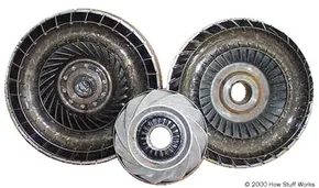

Inside the thick steel shell, four things compete for supremacy. You have impeller. The turbine. stator. There is also transmission fluid It acts as the glue It holds the mess together.
The housing is bolted directly to the engine flywheel. This means you don’t have to worry about gear selection. It spins at any engine speed. The pump fins are attached to this housing. It rotates with the engine. Period.
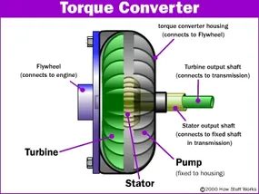
The cross-sectional diagram below shows exactly how these parts are connected.
The mechanical principle of a fluid coupling
Most people think of torque converters as nothing more than a fluid coupling. It’s not. It’s a torque multiplier. This distinction is important when trying to understand why car doesn’t stall at a stoplight.
The impeller is the pump. Powered by an engine. It flings fluid outward. This fluid hits the turbine. The turbine is connected to the input shaft of the transmission. When the fluid hits, the turbine spins. The power is transferred from the engine to the gearbox.
Pretty simple, right?
It gets complicated in the middle.
The stator is located between the impeller and the turbine. This is your secret weapon. The stator changes the direction of the liquid. The direction of the flow changes. This change in direction causes an multiplies torque in torque. Especially at low speeds.
Without a stator you lose a lot of low-end grunt. The liquid just spins for nothing. The stator catches it. Send it back to the impeller. This cycle repeats itself.
Why the Housing Spins
The shell is the anchor. It is bolted to a flexplate. The flexplate is bolted to the crankshaft. Therefore, when the engine rotates, the housing also rotates. No slipping. There are no delays.
The pump is inside this housing. The blade is attached to the inner wall. They rotate at engine speed. This causes stress. Pressure makes fluid move. The fluid drives the turbine.
If the housing is not tightly connected to the engine, everything will fall apart. literally.
Cross section
You can see the layout by looking at the cross-section diagram.
- Outer Ring : Shell. Bolts to the flywheel.
- Internal pump : Connected to the external shell. driving fluid.
- Stator : Attached to a one-way clutch. It cannot rotate freely. The turbine only spins forward if it spins faster than the impeller.
- Turbine : Connected to the gearbox. Drives the wheels (indirectly).
The fluid circulates. In. Out. Around.
It’s not a strong connection. It is hydraulic. There’s slip. You can feel it. At idle, the engine rotates the housing. The turbine is still. The fluid just rotates. No power transfer.
When you press the gas pedal?
The impeller spins faster. The velocity of the fluid increases. The pressure rises. The turbine starts spinning. The lockup clutch engages later in the cycle to prevent slippage. But before It? It’s about fluid mechanics.
The stator remains grounded. Change the direction of the returning liquid. This increases torque. Therefore, you can creep forward in traffic without stalling. The converter doubles the power of the engine.
It’s very messy. It

Working principle of the torque converter impeller
The impeller works as a centrifugal pump. It is located inside the torque converter. When the engine rotates, the fluid is splashed out to the outer edge. Think about your washing machine. The spin cycle hits the water and clothes against the walls of the drum. The impeller does the same thing to the transmission fluid.
This outward force creates a vacuum in the center.
The vacuum absorbs more liquid. This is a continuous cycle. The liquid comes out. More fluid flows in. This cycle creates the hydraulic pressure needed to transfer power from the engine to the transmission. Without this suction power, the converter will not work. The liquid should continue to flow. Otherwise, power transfer stops dead.
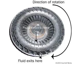

When the transmission fluid leaves the pump, it hits the turbine blades. This is not just passive movement. The turbine is locked to the input shaft of the transmission, so when the fluid hits these vanes, it forces the shaft to rotate. The power is transmitted through axles and differentials and finally reaches the drive wheels.
Look at the shape of the blade. They are curved. Fluid comes from the outer edge and must flow back to exit through the center hub. Changes in trajectory create torque.
Newton’s third law applies here without exception. When you change the direction of an object, a force is applied to it. Objects exert equal and opposite forces. The blades of the turbine force the fluid inward and reverse its flow. The fluid pushes the blade back. This pushing causes the turbine to rotate.
However, there is a problem with exit flow. When the fluid exits the turbine, its motion is exactly opposite to the direction of rotation of the pump or engine. When the flowing fluid hits the pump impeller again, it acts as a brake. This consumes the engine’s energy and reduces its efficiency.
This is why a torque converter requires a stator.
The role of the stator in torque conversion
The stator is located between the turbine and the pump. It does not rotate as freely as the other two components. Its job is to redirect the fluid leaving the turbine so that it hits the pump in the right direction.
Without a stator, the torque converter is just a fluid clutch. It transfers energy but does not add energy. With the help of the stator, the converter can increase the torque of the engine, especially at low speeds. This is why you feel the power increase when accelerating from a standstill. The stator locks up and reverses the flow direction, creating a feedback loop that amplifies the force.
When is the stator locked?
The stator does not always remain locked. As the speed of the car increases, the turbine approaches the speed of the pump. The fluid exiting the turbine no longer flows strongly backwards to benefit from the change in direction. At this time, the one-way clutch of the stator is released.
The stator starts rotating along with the rest of the assembly. There is hardly any resistance. The torque converter is actually a fluid clutch. This reduces drag and improves fuel efficiency at highway speeds.
Torque multiplication and direct drive
Understanding the stator explains why manual transmissions feel slower than automatics. The torque converter increases the torque of the engine under the influence of the stator. Manual clutches only depend on engine speed and friction material. Converters smooth the transmission while increasing power.
This design option has trade-offs. Fluid clutches are inherently less efficient than mechanical clutches. There will always be some slip. But the key is the trade-off between smoothness and increased torque.
The stator is the unsung hero of the automatic transmission. This increases torque and makes heavy vehicles feel lighter off the line. Without this, all automatic cars would need huge engines to operate as well as small displacement manual cars.
The following section describes the mechanical details of the stator one-way clutch.
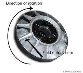

The stator is located at the dead center of the torque converter. It redirects the fluid returning from the turbine before it reaches the pump again. This simple measure increases efficiency.
The stator blades are aggressive. They almost completely reverses the flow of liquid. A one-way clutch in the stator locks it to a fixed shaft to the fixed shaft. The direction in which the clutch allows spin is certain. This setting means that the stator cannot rotate with the fluid. Only reversing is possible. This causes the liquid to change direction when it hits the blade.
Things get tricky once things can get difficult. On the highway, the impeller and the turbine rotate at approximately the same speed. The pump is always a little faster. But they are close. A stator is not needed at this time.
The liquid returning from the turbine enters the pump, which already moves in the same direction as the pump.
Imagine standing behind a pickup truck moving at 60 mph. You throw the ball from behind at 40 miles per hour. The ball is still moving forward at 20 miles per hour. The same principle applies to turbines. The turbine rotates at high speed in one direction. It sprays liquid from behind, but not as fast as the original forward speed. The liquid still travels forward relative to the pump.
When the car reaches these speeds, fluid hits the back of the stator vanes. The stator rotates freely with the help of a one-way clutch. Spin freely. Does not block flow.
Advantages and disadvantages of torque converter

Multiplication Trick
Do you think braking will stop the car? Wrong. The torque converter plays an important role here. Prevents the engine from shutting down when stopped at a red light. But there is more to it. It works like a force multiplier.
The torque converter increases the engine’s torque by two to three times when the pedal is pressed from a standstill. This magic only works if the engine spins much faster than the transmission. Slippage creates the torque multiplication.
High-Stall Converters Explained
Street cars use standard converters. Perfect for traveling. But what about drag racers? They want something different.
High-stall converters are the answer. They delay the lockup. This allows the engine to rev higher before power is transferred to the wheels. No time is wasted with low revs. When the engine approaches peak power, the launching the car.
This is great for the track. Too bad for the commute. In everyday traffic situations, a high-stall converter can makes your car sluggish. It hunts for gears. It will be a waste of fuel. This is a niche tool for a specific job.
Reduced efficiency
This is the ugly truth about automatics. When driving on the highway, the engine and transmission speeds are different. The transmission lags behind. It typically runs at about 90% of engine speed.
This 10% difference is not free. Energy is lost. Heat is generated when the fluid churning inside. Power is lost to the atmosphere. For this reason, automatic transmissions usually have worse fuel economy than manual transmissions. Sliding is continuous. This inefficiency adds up.
Lockup Solution
Engineers hate waste. So they invented the lockup clutch.
When the torque converter reaches cruising speed, the clutch engages. Physically lock the two halves together. The engine and gearbox rotate at the same speed. No slipping. No heat. No power loss.
This simple mechanical connection can restore lost efficiency. Bring automation closer to manual performance.
Gear Count Wars
But the lockup clutch alone is no longer enough. Gear ratios in modern automatic cars are crazy. Up to 10 gears forward. Why? Keeps the engine in optimal position. The more gears you have, the less the engine has to rev at the same high speed to maintain speed.
Older manuals had five or six gears. Today’s cars have even more. optimize power delivery better. They mimic the efficiency of older manual designs, but also have the convenience of automatic.
Is it perfect? No, it’s very complicated. But it works. Torque converters have evolved from simple fluid couplings to complex, efficiency engine. It’s a marvel of hydraulic engineering disguised as a simple bowl-shaped component.
I never see the lockup clutch engaged. You won’t feel the torque multiplication. It just happens. under the hood. In the dark. Where it belongs


