Most car owners don’t give their brake lights a second thought until they stop working. Then, panic sets in. Is it the bulb? The fuse? Or something deeper in the wiring harness? Understanding a basic brake light wiring diagram isn’t just for professional electricians or die-hard gearheads. It’s a survival skill for anyone who wants to avoid a ticket or a rear-end collision. The system seems simple: step on the pedal, lights glow red. But beneath that simplicity lies a network of circuits, switches, and safety interlocks that deserve a closer look.
The Core Components
Before diving into the diagram, you need to know what you’re looking at. Every standard automotive brake light setup involves three main players. First, there’s the brake light switch. This is usually mounted near the brake pedal. When you push the pedal down, the switch closes, sending power into the circuit.
Next is the fuse. This protects the entire system from short circuits and electrical surges. It’s typically located in the vehicle’s main fuse box, either under the hood or inside the cabin. If your brake lights are dead, checking the fuse is always step one.
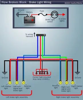
Finally, there are the bulbs themselves. These can be traditional incandescent bulbs, LED modules, or a mix of both, depending on the vehicle’s age and trim level. The wiring diagram maps out how power flows from the fuse, through the switch, to the bulbs, and finally to the ground.
Reading the Diagram
A wiring diagram might look like a spiderweb, but it follows a logical path. Start with the power source. In most modern cars, this is the battery, routed through a main fuse. The line then leads to the brake light switch. The switch acts as a gatekeeper. When it’s open (pedal not pressed), no current flows. When it’s closed (pedal pressed), the circuit completes.
From the switch, the wire splits. In many vehicles, the brake light circuit is shared with the tail lights. This is why your rear lights often dim slightly when you hit the brakes—they’re receiving power from both the headlight circuit and the brake circuit. The diagram will show this junction clearly. Look for a point where two wires merge before entering the left and right tail light assemblies.
Common Wiring Colors and Locations
While wiring colors can vary by manufacturer, there are some standard conventions. Red or yellow wires often carry power, while black or brown wires are typically grounds. Blue or green wires might be for turn signals or reverse lights. If you’re troubleshooting a specific issue, knowing the wire color can save you hours of probing with a multimeter.
For example, in many American cars from the 1990s and early 2000s, the brake light switch uses a two-wire connector. One wire brings power in, and the other sends it out to the lights. Some newer vehicles use a single-wire system with a ground return, or even a digital signal via the vehicle’s computer network. Understanding this difference is key to diagnosing why your brake lights might be flickering or staying on when they shouldn’t.
Why the Diagram Matters
You might think, “I’ll just replace the bulb.” And you’re right. Often, that’s all it takes.